Asymmetry/Overspeed Brake Test Stands
The Problem
Certain aircraft functions such as high lift devices (flaps) must not be allowed to develop asymmetries. It is critical to flight safety that the flap configuration on both wings be identical. Unfortunately, mechanical failures in the flap drive system may cause one flap to remain extended while the other "flies" back to the retracted configuration. The resulting roll moment would likely be catastrophic.
Solution
 Asymmetry brakes (A-brakes) are designed to stop such a situation from developing. They can do this electrically using position sensors and they can respond mechanically to sudden, accidental movements such as those experienced in drive shaft failures. Testing these A-brakes is challenging since very high acceleration rates (>40,000 rad/sec2) are required to simulate flight conditions.
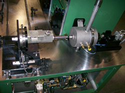
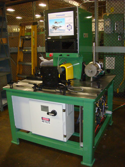
 The Emprise A-brake test stand provides a simple, reliable way to apply the static torques, rotational speeds and accelerations required by qualification and functional test procedures. A manual torque station allows the operator to apply proof loads while the data is automatically recorded in the computer data system. The centrally mounted variable speed electric motor applies the needed overspeed check points and allows electrically initiated trips to be exercised. An inline magnetic clutch limits the stopping torque to protect the test article from the motor inertia.
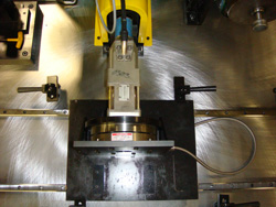
 The acceleration trip check is more difficult because high accelerations are required and because the acceleration generator must not be so massive that destructive loads are experienced in the lock-up event. Emprise uses a very simple piston and pulley device to accomplish the required test. Much like an old rope pull starter, a cable is wrapped around a drive shaft pulley and connected to a small piston/cylinder arrangement. The system is charged to a precise pressure (either shop air or cylinder gas) and the trigger is released. As the piston travels down the cylinder, the cable turns the pulley and test article at an acceleration proportional to the pressure. A very linear and repeatable angular acceleration is produced. When the lock-up occurs, the test apparatus inertia is very small so no damage is done to the test article.
Emprise can design these accelerators to suit your needs. In the example shown we used two ¾" pistons to achieve a 40,000 rad/s2) result at 178psig. Other requirements might dictate different design parameters but the principle is the same. This same device may be used where a controlled and linear acceleration is required. Other uses might include angular overspeed brakes, rotary bearings, acceleration sensors and rotary encoders.